

 |
 |
 |
 |
 |
 |
 |
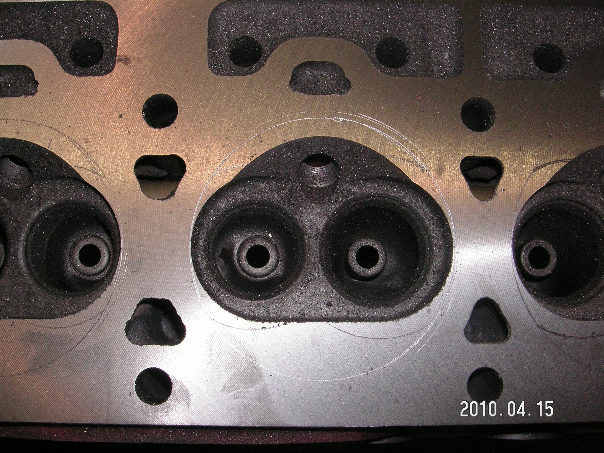
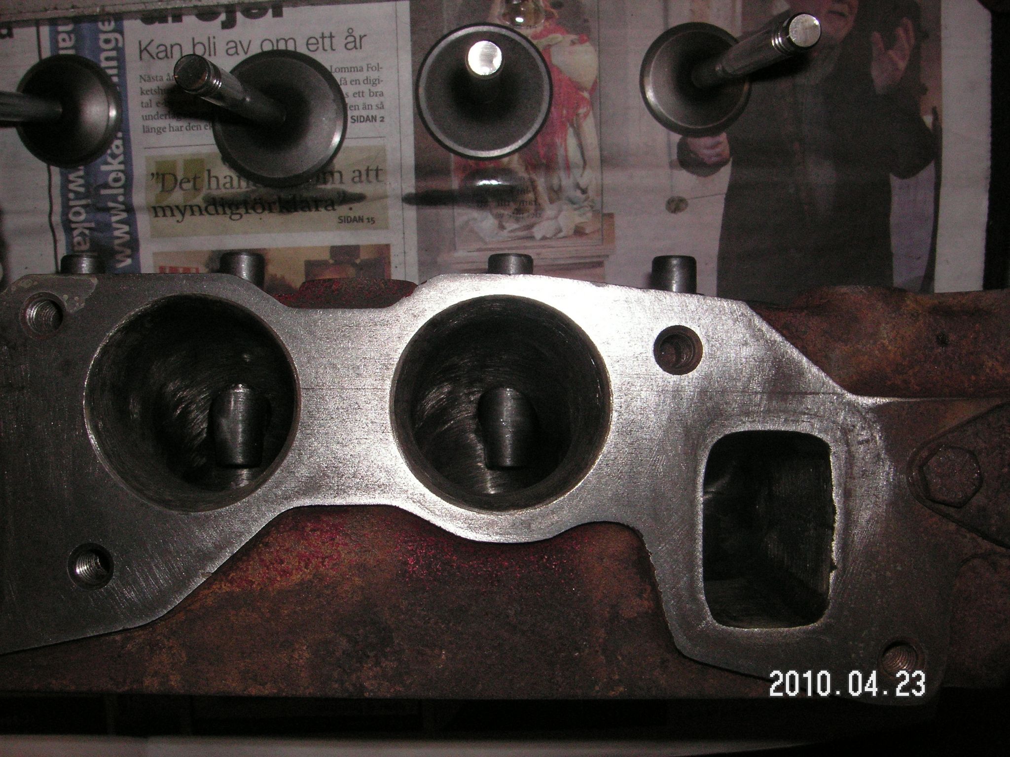
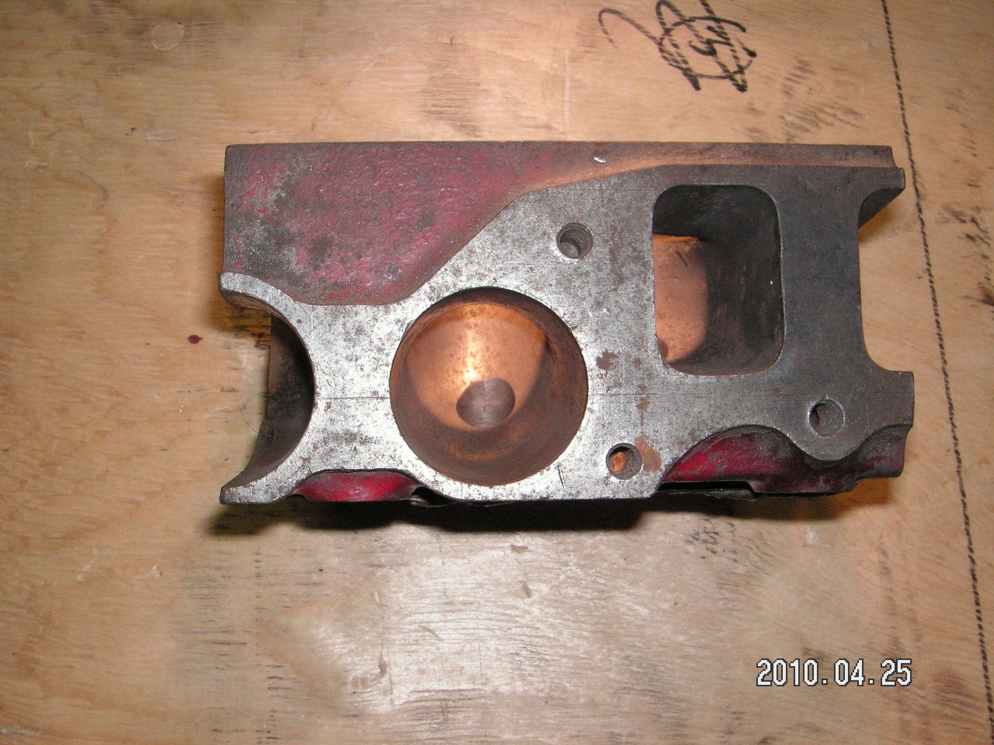
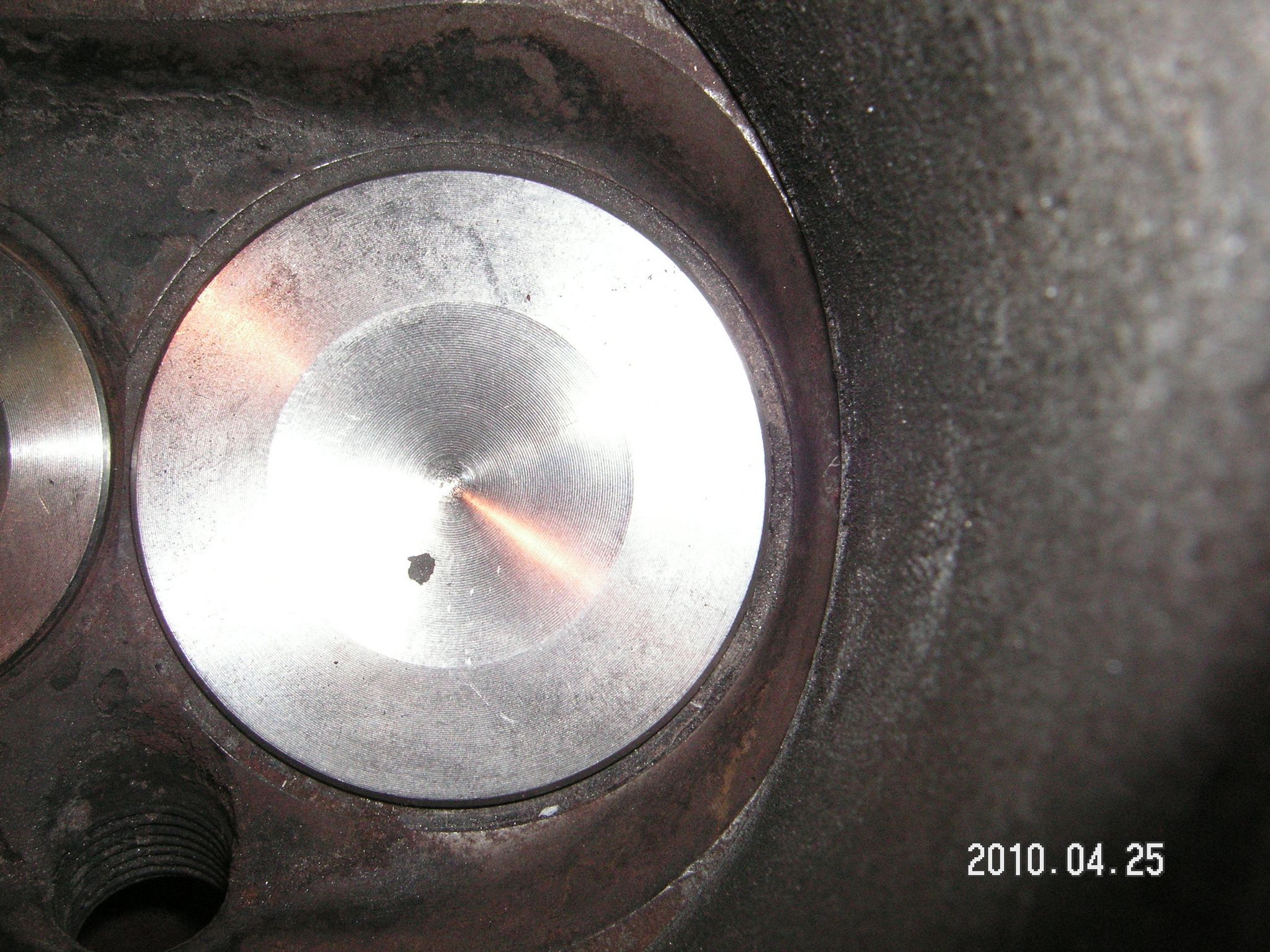
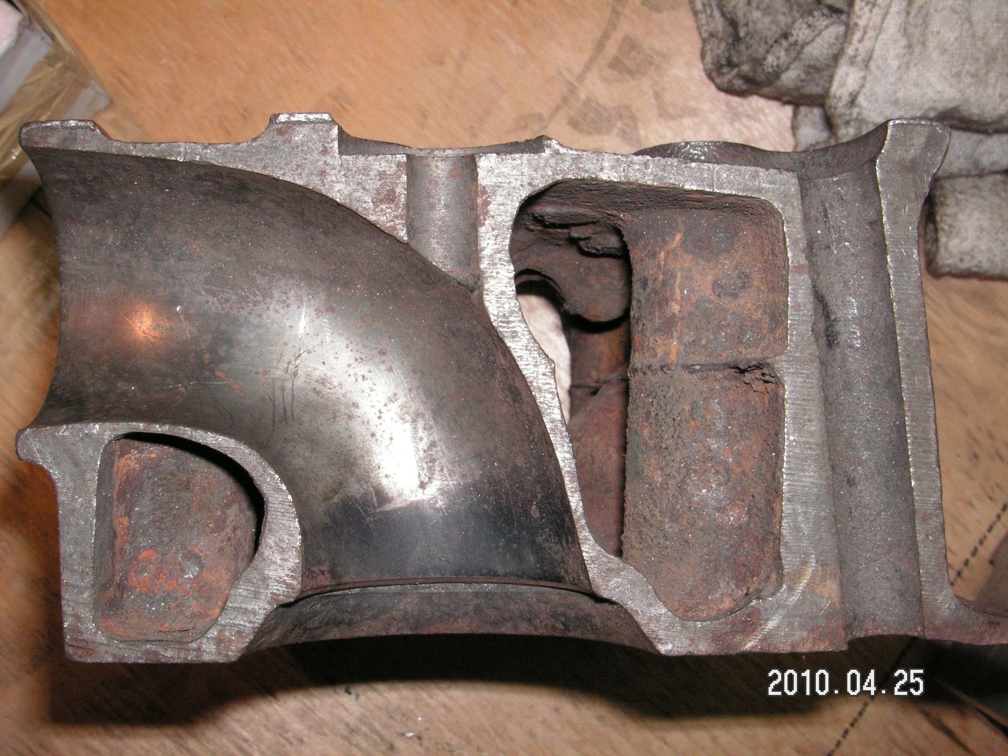
I bilden ovan syns det hur jag ritsat toppen efter cylindern och att jag ritsat med ett par stora ventiler som motsvarar ventilernas plus mantelytornas areor. Detta använder jag som utgångspunkt när jag slipar förbränningsrummen. |
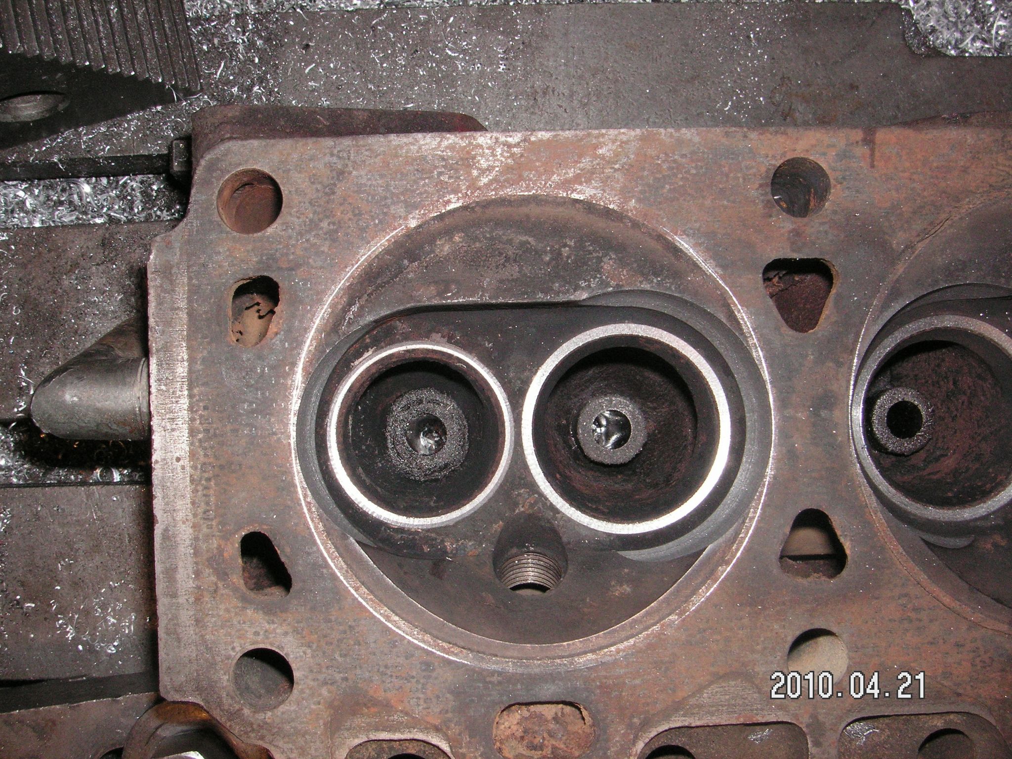
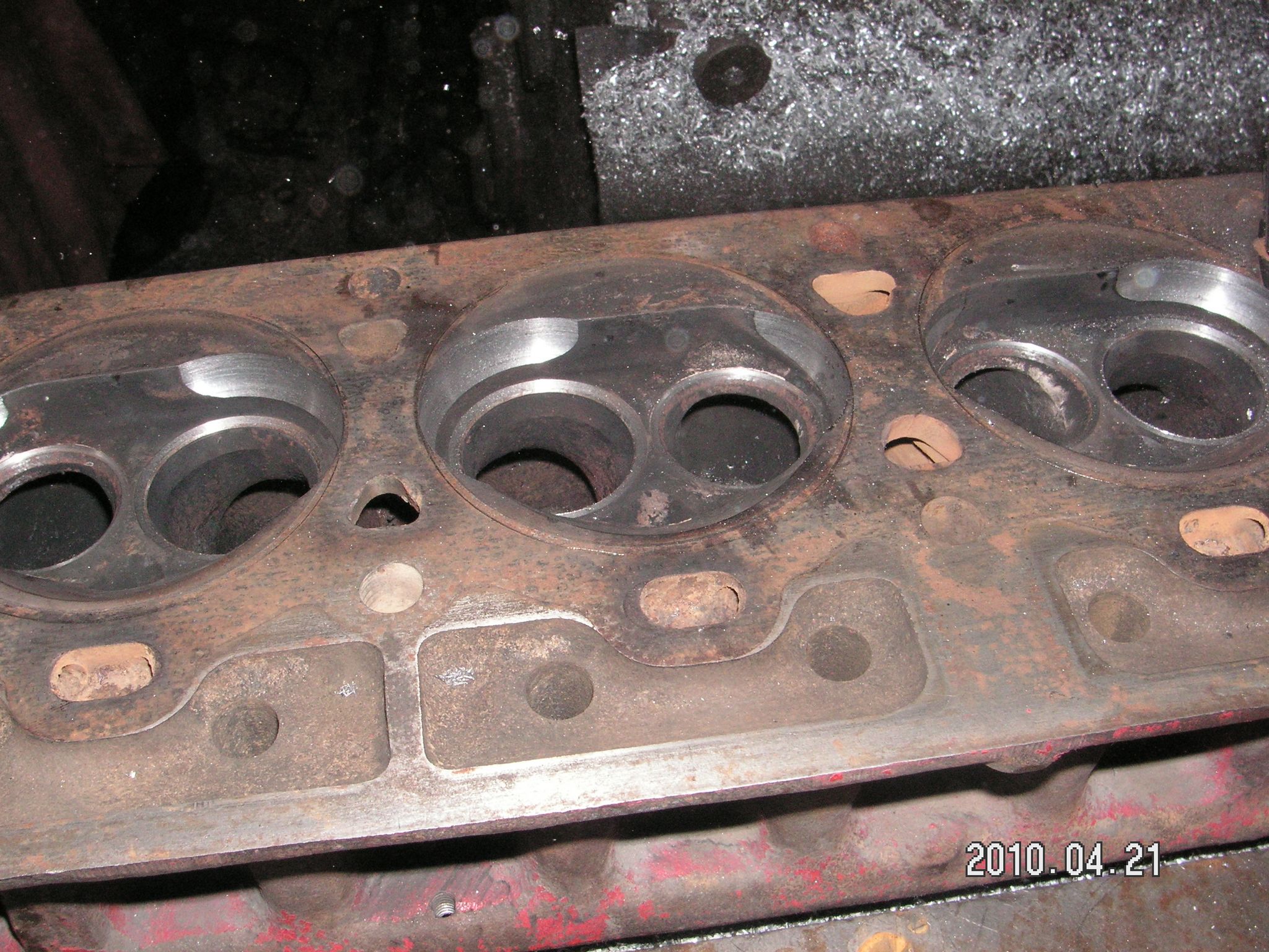
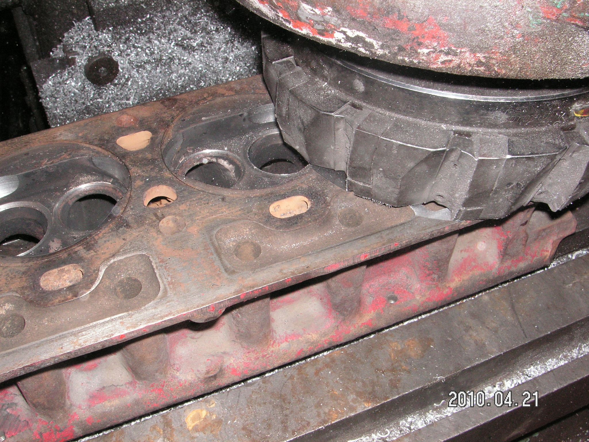
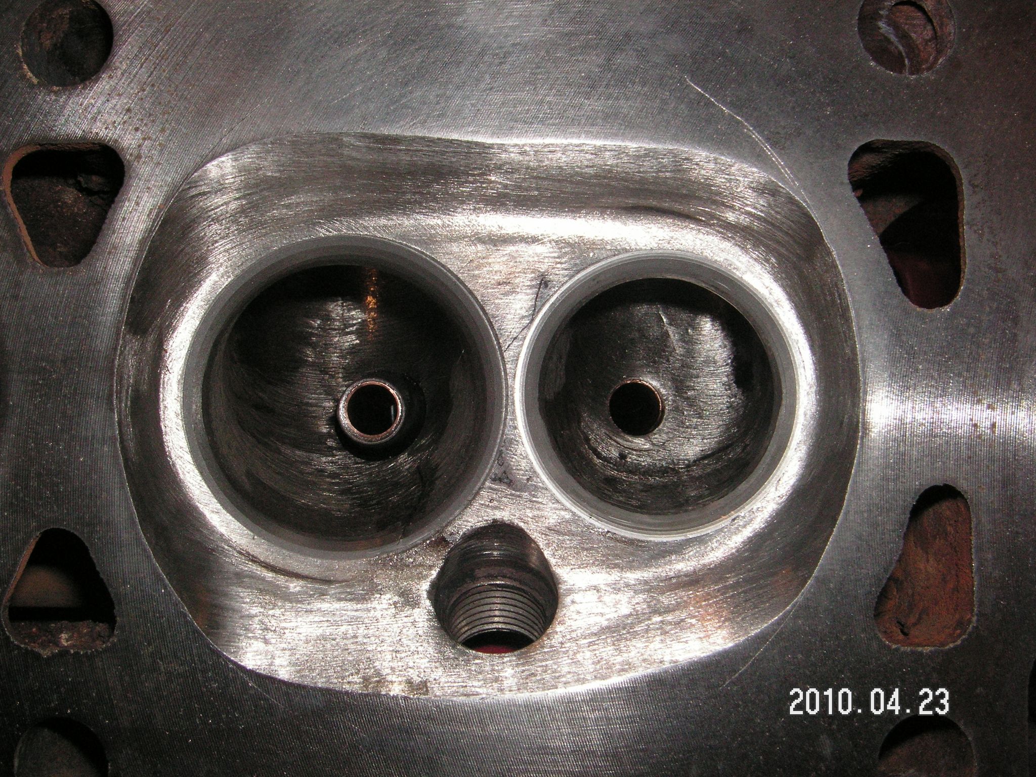
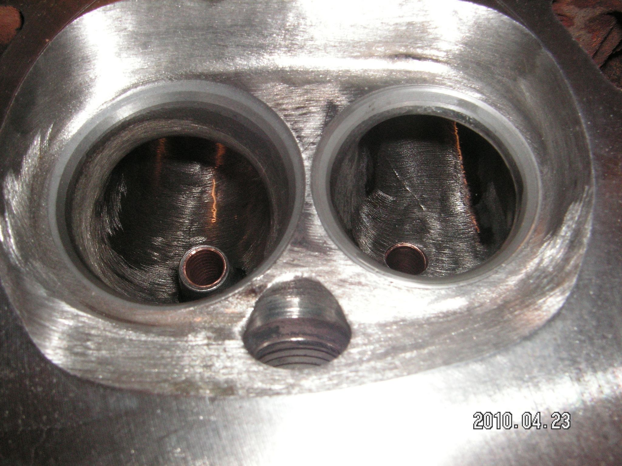
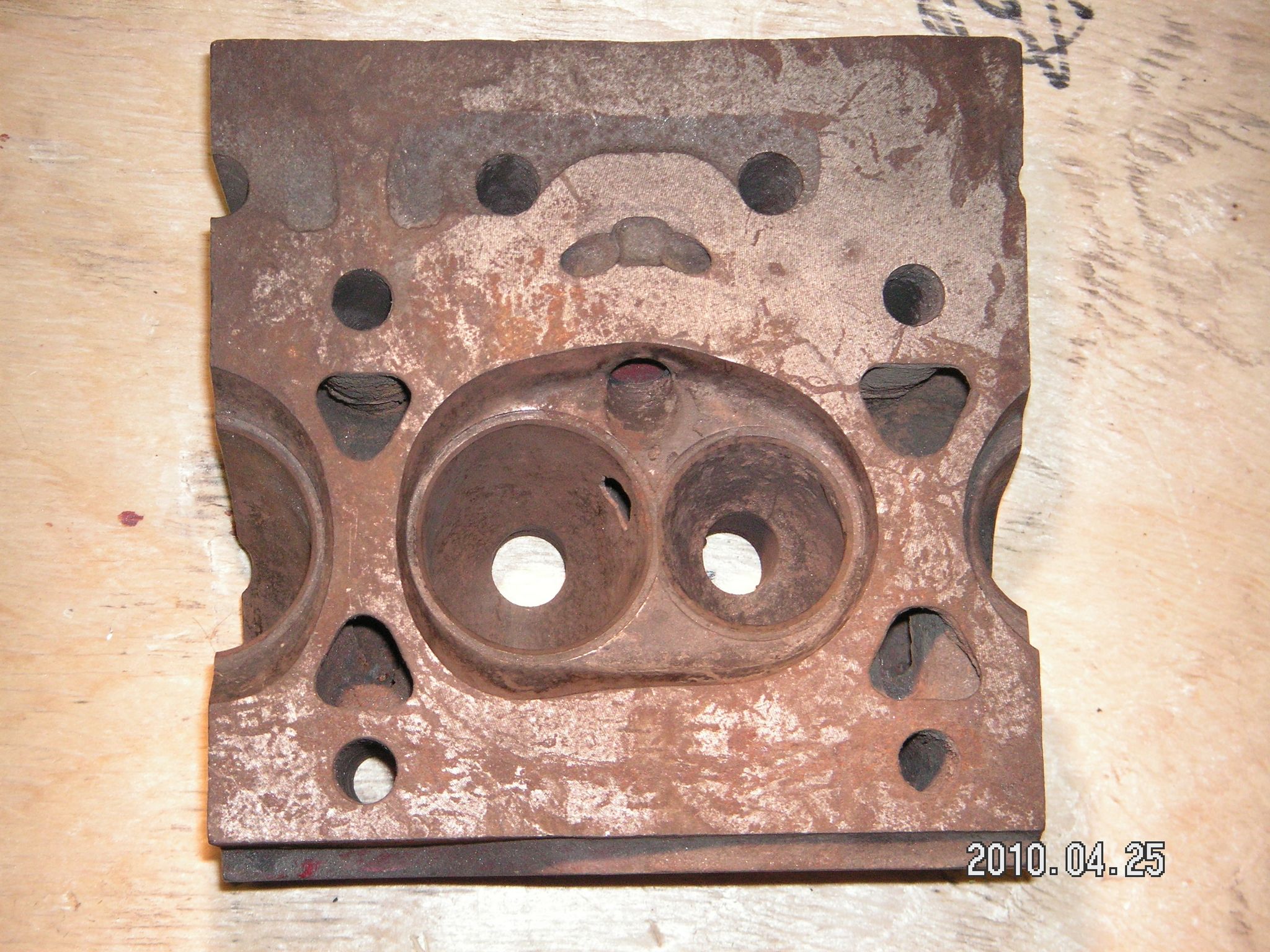
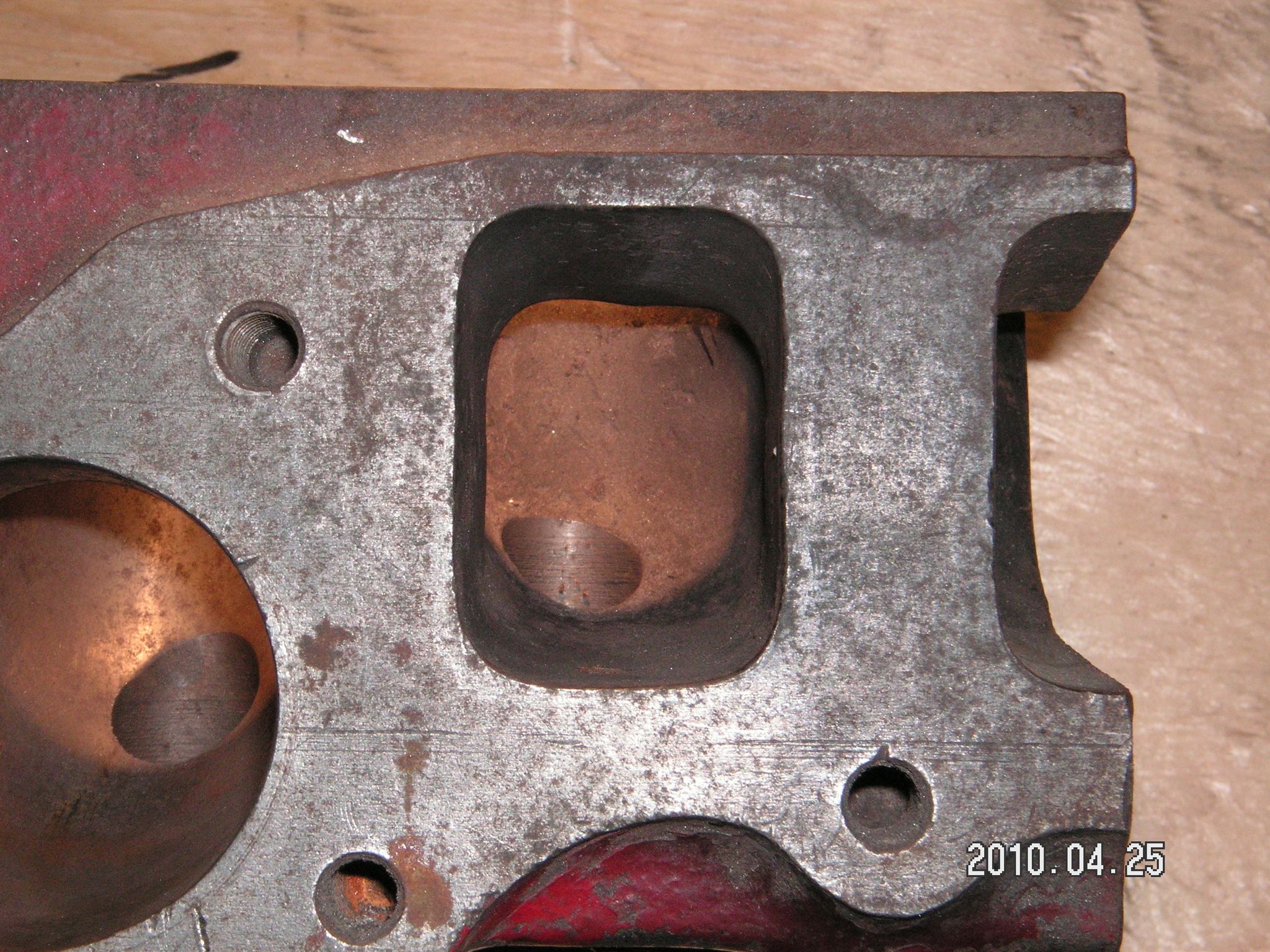
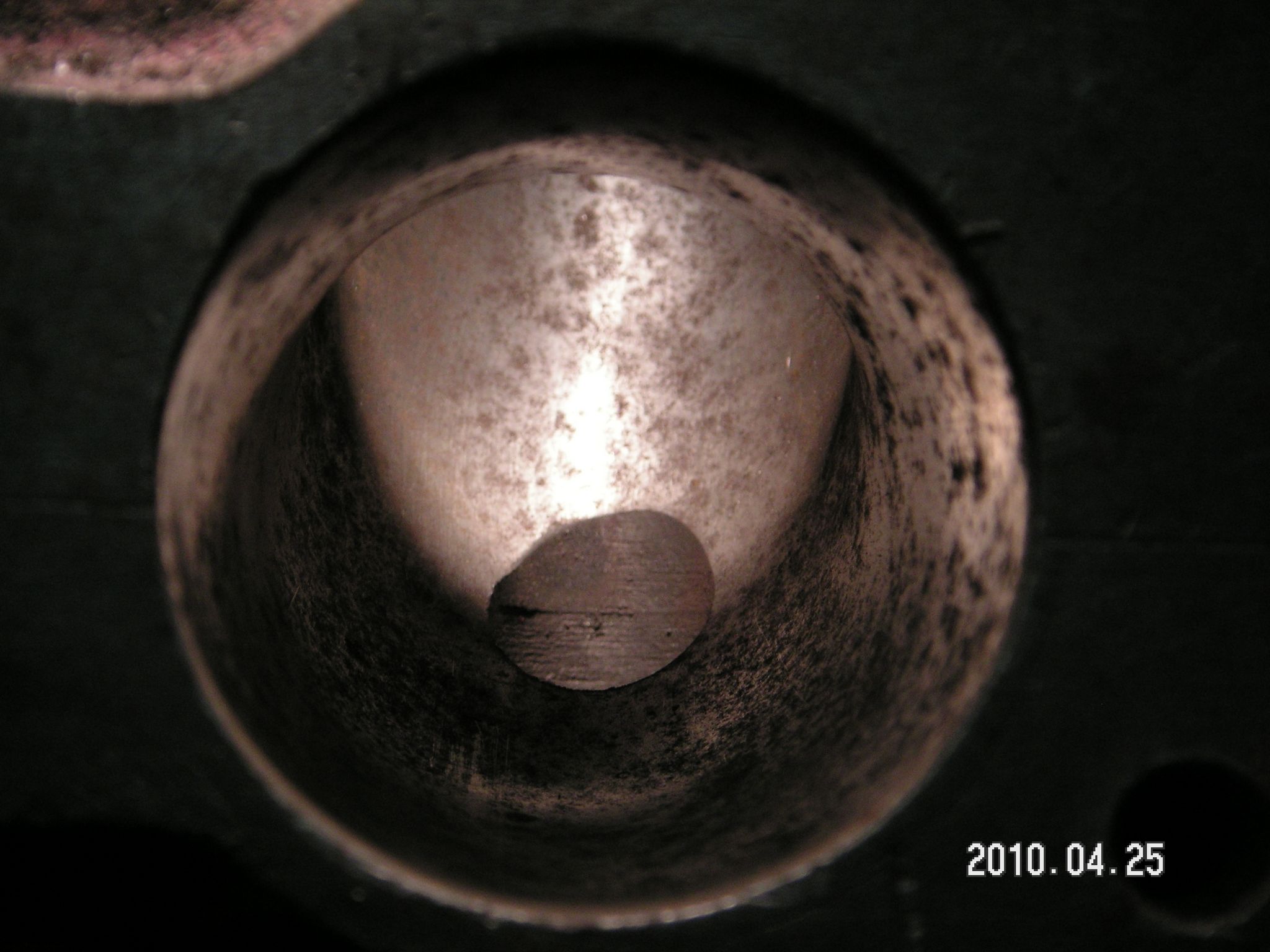
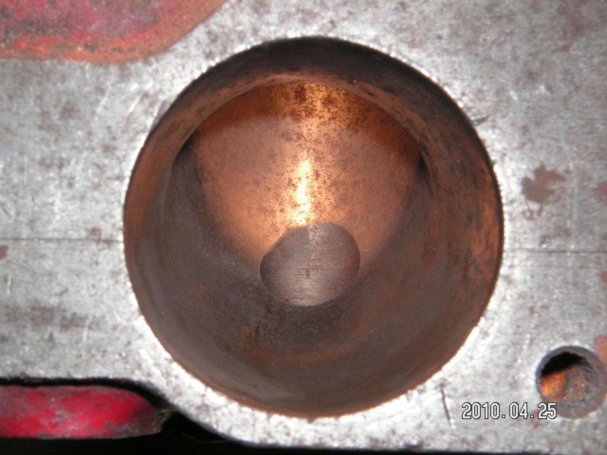
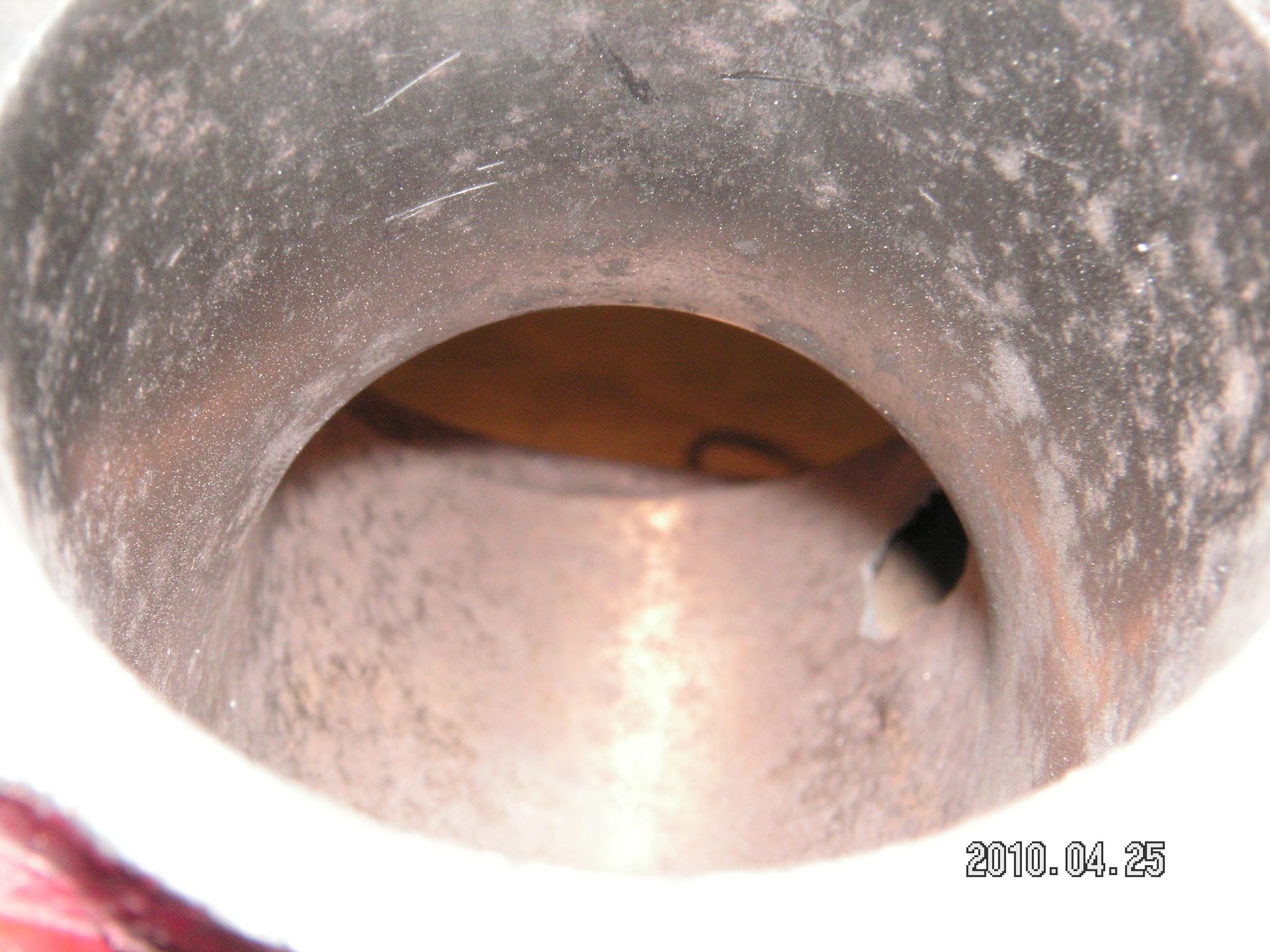
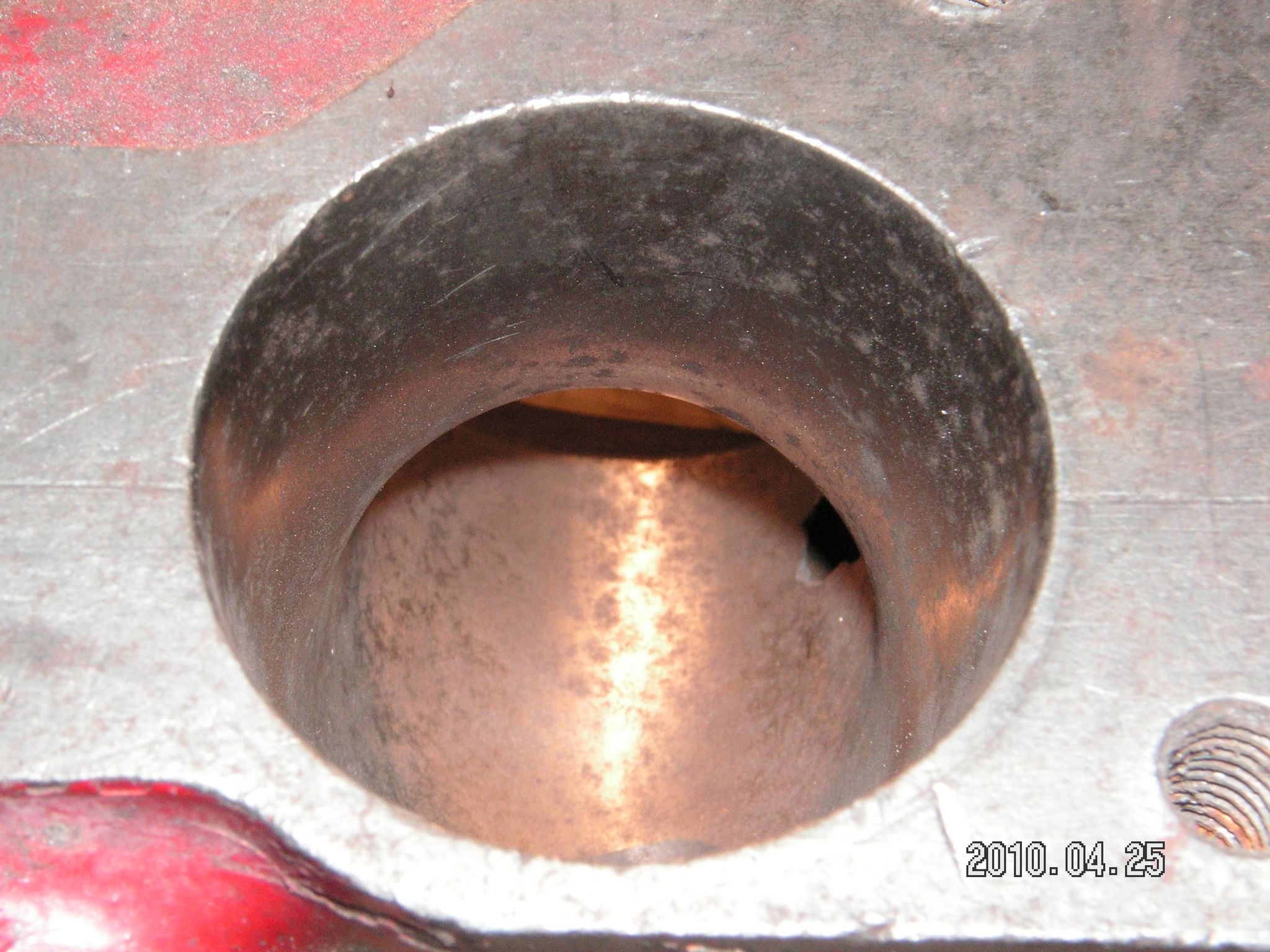
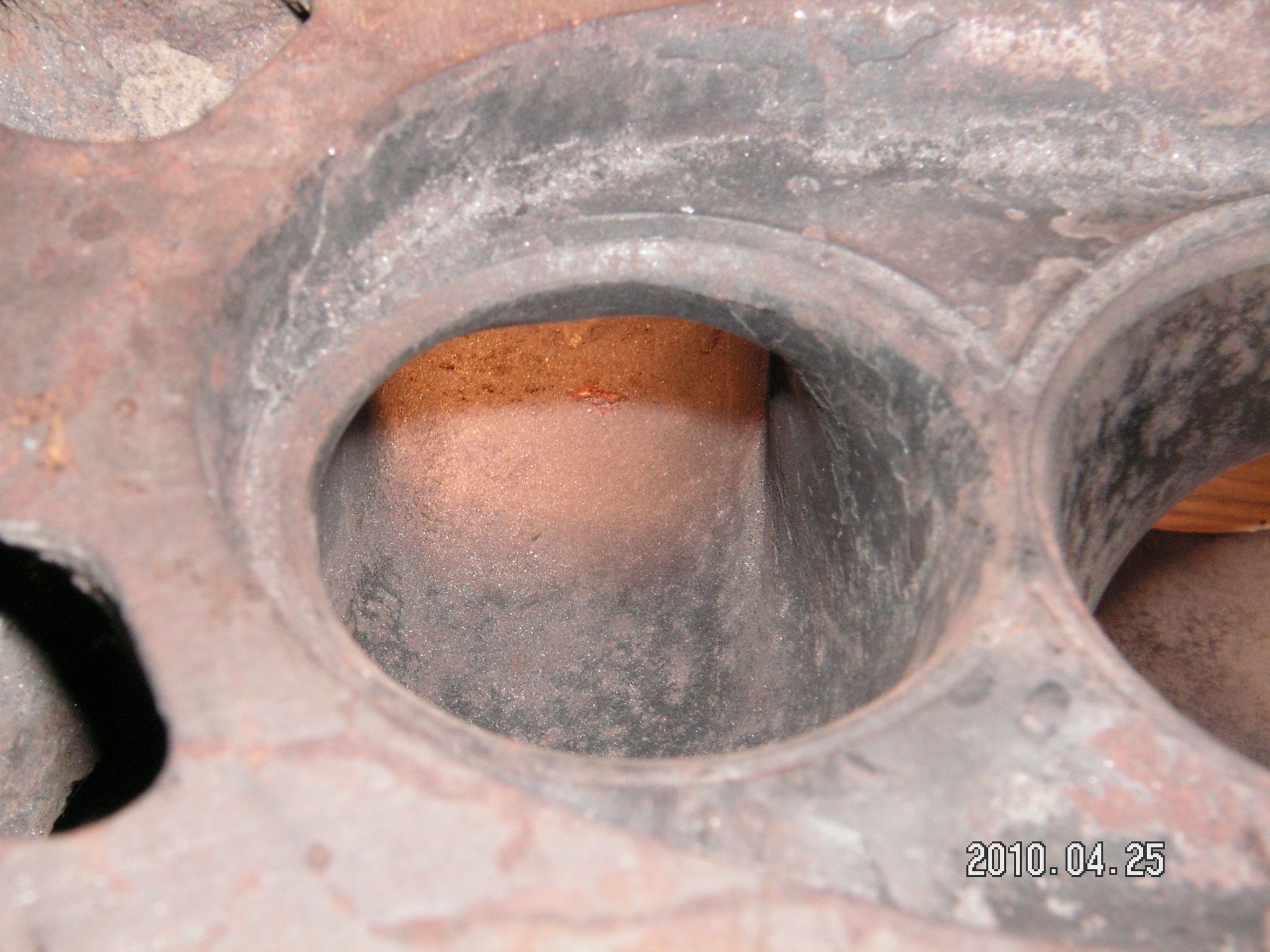
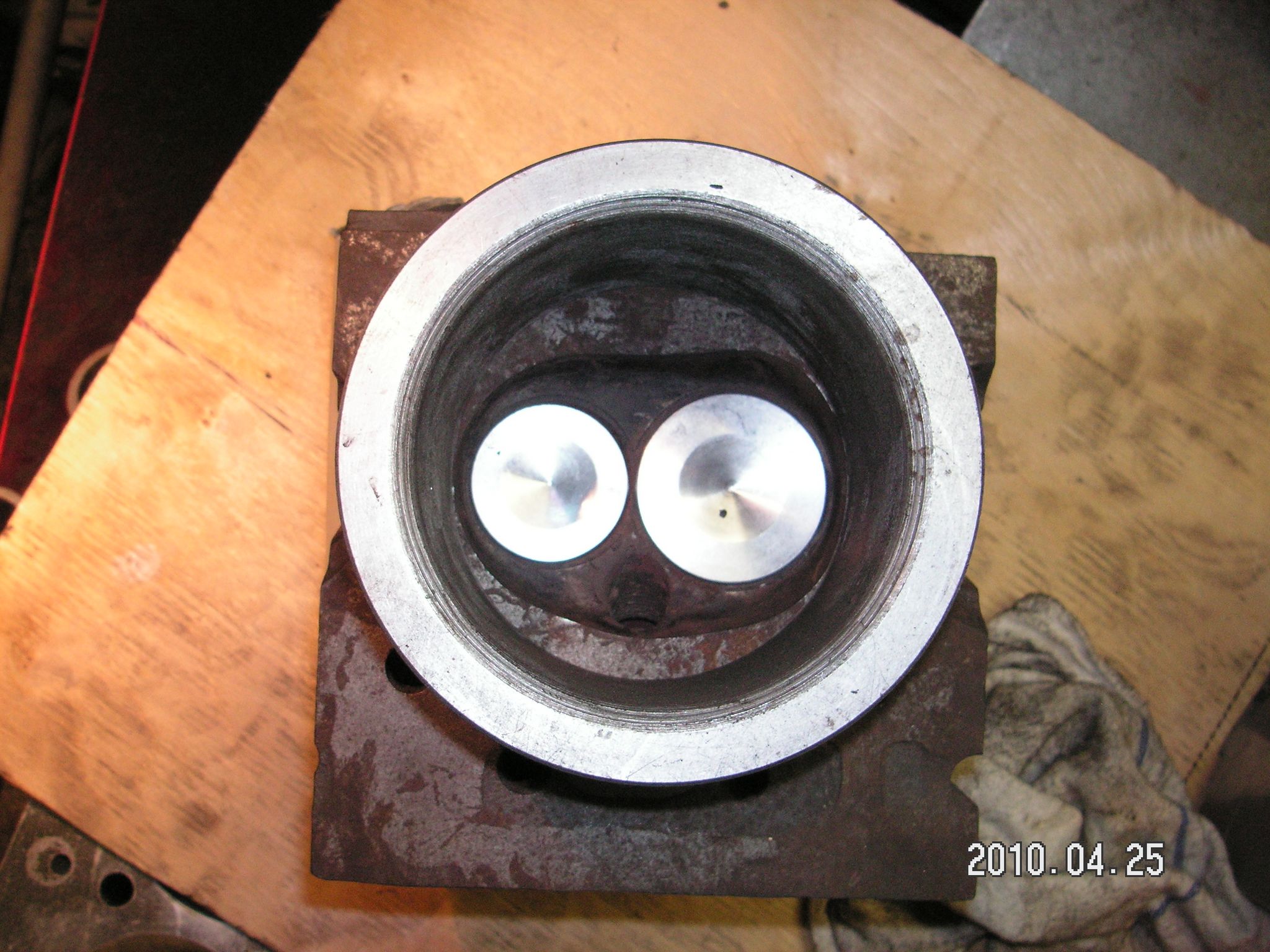
| Toppen ovan är avsedd för historisk racing och till en cylinderdiameter som inte är större än 89 mm. Jag valde att utgå från ett B18 toppämne eftersom denna topp har ventilerna 1 mm längre in mot centrum. Den har däremot inte lika stor insugnings kanal som de nyare topparna. Jag valde att använda 42-35 ventiler. 42 mm insug eftersom en större ventil inte skulle få 12% av sin diameter i spalt mot cylinderväggen. Med B18 ämne och 42 mm:s ventil blir spalten 4.5 mm vilket inte är 12% utan 10.7%. Så till och med denna i Volvo sammanhang lilla ventil är spalten för liten. Hade jag använt ett B20 ämne istället så hade spalten bara blivit 3.5 mm. Med den topp som tidigare satt på och som var ett B20 ämne med 46 mm:s insugningsventil var spalten endast 1.5 mm. Bilderna nedan visar en B20 racing topp som har haft 46-38.5 ventiler tillsammans med en flödescylinder som är 92 mm. Flödesvärdena som kommer längre ner är gjorda med denna cylinder eftersom jag inte har någon 89 mm:s. 46-38.5 toppen som jag ersatte och som inte är den på bilderna hade alltså flödat betydligt sämre när cylinderväggen hade kommit 1.5 mm närmre ventilerna. |
 |
 |
 |
 |
 |
 |
 |
 |
 |
 |
 |
 |
 |
 |
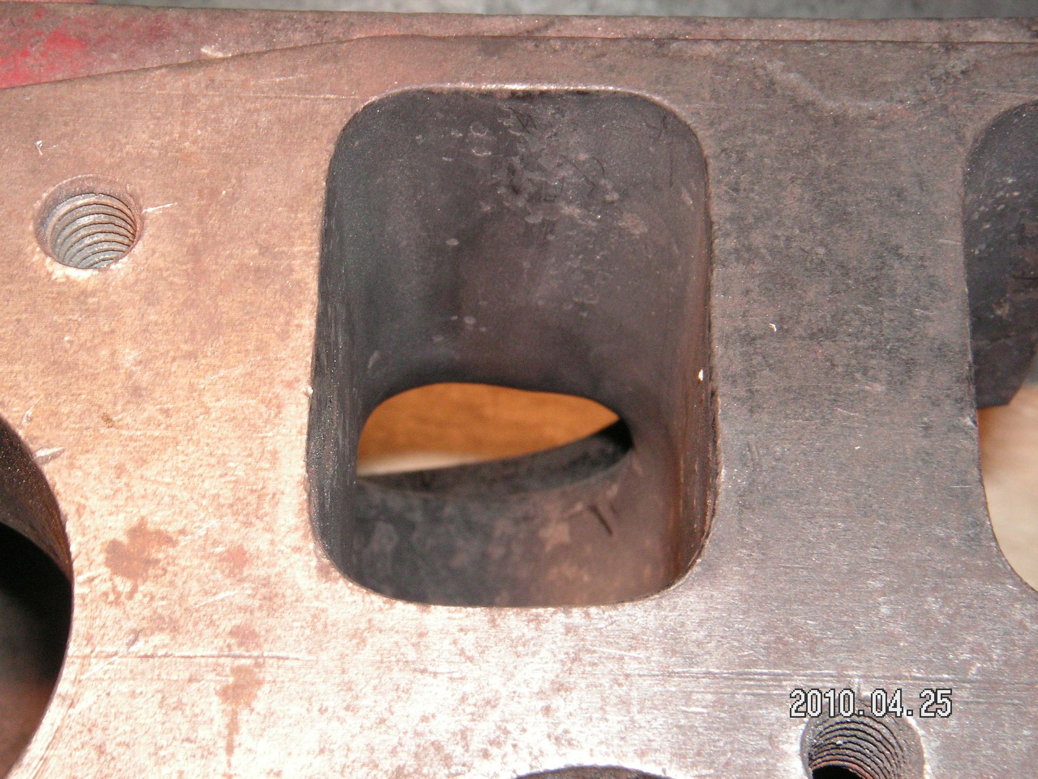
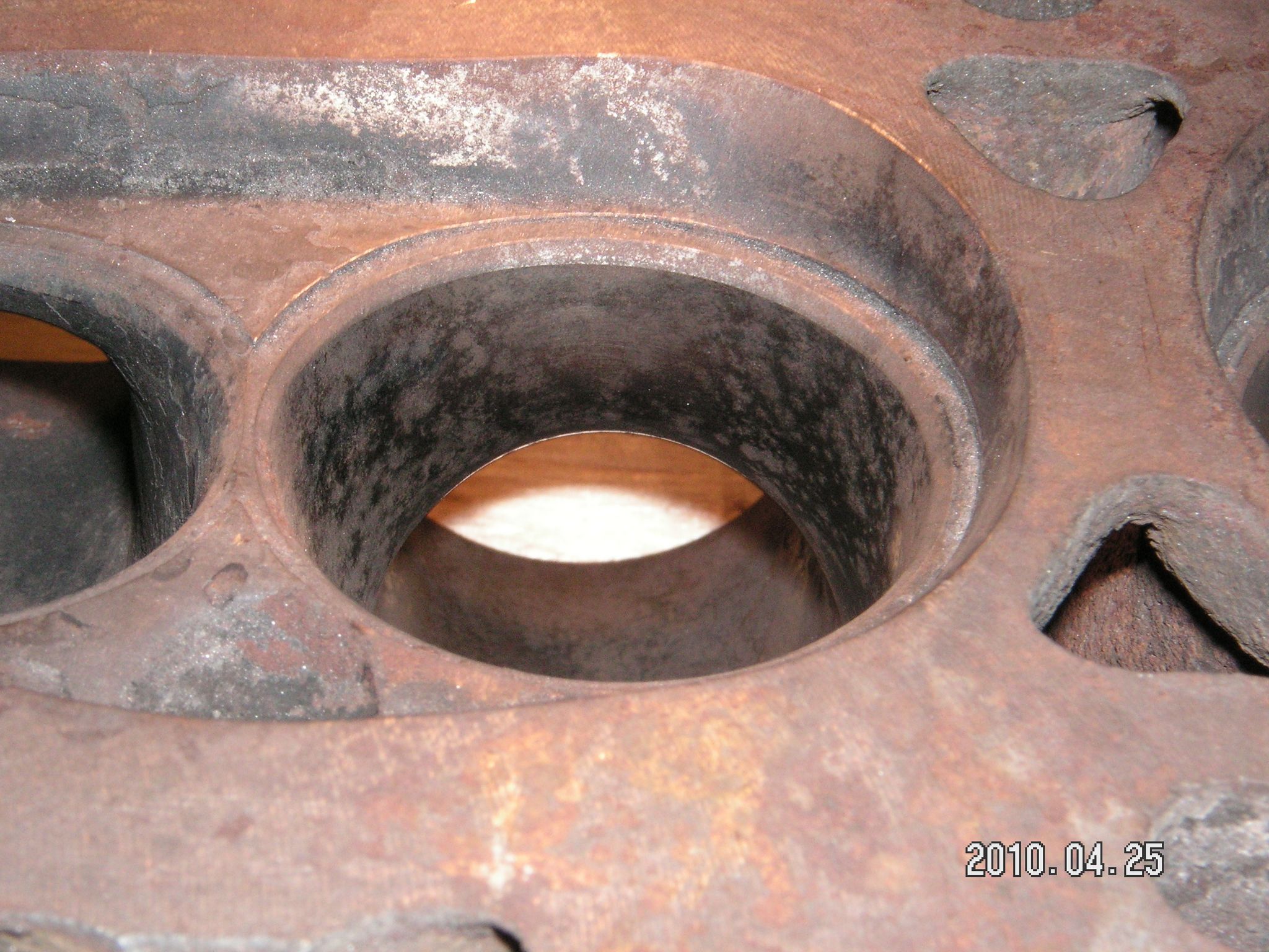
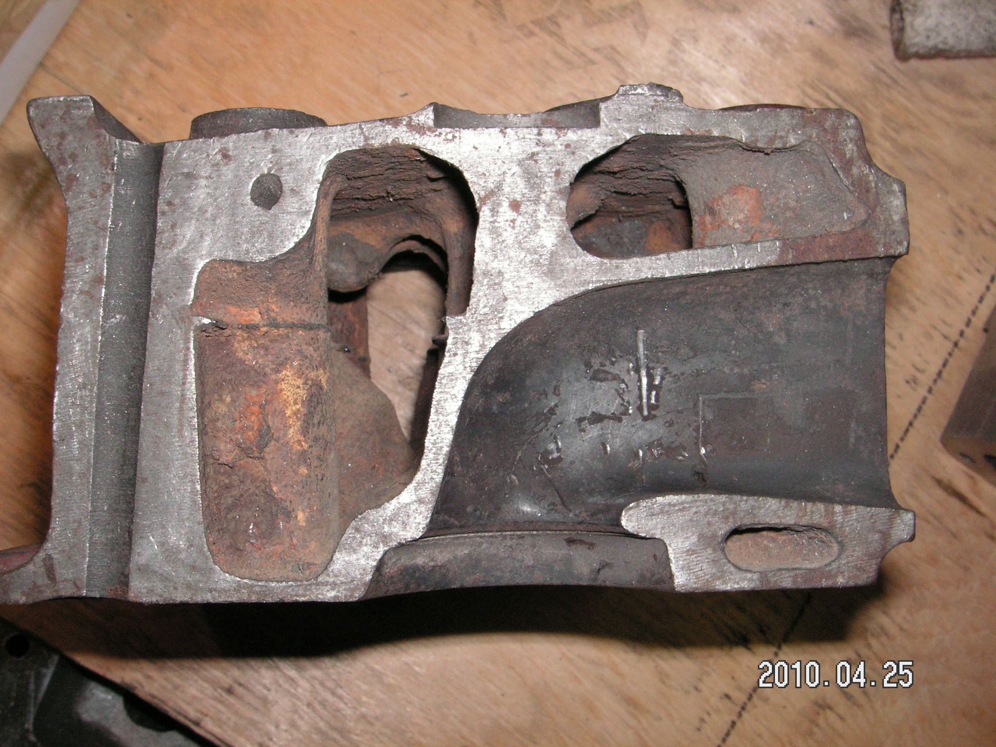
Den här gamla racingtoppen är rejält portad och har en minsta diameter som är större än 38 mm. Toppen jag ersatte var också ganska stor i kanalen förutom mitt mellan inloppet och svängen ner mot ventilen där den endast var 35.5 mm. B18 ämnet portade jag så att minsta arean hamnade mellan svängen och sätet och den var också 35.5 mm. Att jag inte använde större avgasventiler än 35 mm är för att jag anser att det inte behövs större och att jag tror att man förlorar effekt med större avgasventiler. Likaså tror jag inte på mer avgasduration än insugningsduration. Att det trots allt brukar fungera beror på att grenrören har för långa primärrör. | |
 |
|||
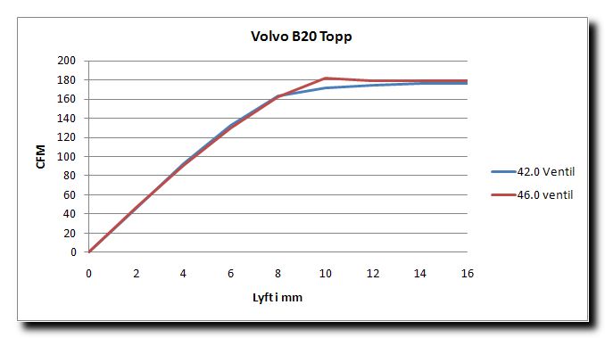
| Lyft i mm | 42.0 Ventil | 46.0 ventil | |
| 0 | 0 | 0 | |
| 2 | 45.7 | 47.1 | |
| 4 | 92,8 | 90,5 | |
| 6 | 132,4 | 129,7 | |
| 8 | 163,5 | 162,6 | |
| 10 | 172,1 | 182,2 | |
| 12 | 174,5 | 179,5 | |
| 14 | 176,2 | 179,8 | |
| 16 | 176,6 |
179,8 | |
 |
|||
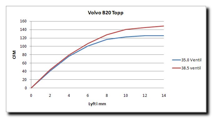
| Lyft i mm | 35.0 Ventil | 38.5 ventil | |
| 0 | 0 | 0 | |
| 2 | 41.2 | 44.2 | |
| 4 | 75.7 | 79.1 | |
| 6 | 100.7 | 107.1 | |
| 8 | 116.4 | 128.2 | |
| 10 | 122.4 | 140.3 | |
| 12 | 125.1 | 145.3 | |
| 14 | 125.1 | 148.9 | |
| Till de här flödningarna har jag använt 92 mm:s cylinder som är 3 mm större än motorns verkliga cylinderdiameter. Att ett för långt avgasgrrenrör fungerar tillsammans med för lång duration beror på att det längre röret kräver mer duration för att tuna på samma varvtal. Ett längre rör gör att pulsen måste färdas längre och detta tar längre tid. Öppnar man ventilen tidigare och stänger den senare så hinner pulsen fram och tillbaka ändå. Rätt lösning är ett kortare avgasgrenrör. 46-38.5 toppen flödar 85% av insug på avgas vilket är alldeles för mycket. 42-35 toppen har fullt tillräckliga 75% av insugningsflödet på avgas. |
| Jag har gjort en Pipemax beräkning för en 2 liters motor som lämmnar 180 hk vid 6500 varv |
Required Intake Flow between 162.7 CFM and 171.2 CFM at 28 Inches 600 RPM/Sec Dyno Test Lowest Low Average Best HorsePower per CID 1.412 1.470 1.499 1.528 BMEP in psi 190.8 198.6 202.5 206.5 Target EGT= 1254 degrees F at end of 4 second 600 RPM/Sec Dyno accel. test Peak HorsePower calculated from Cylinder Head Flow CFM only ----- Engine Design Specifications ----- Intake Valve Margin CC's Exhaust Valve Margin CC's ------- Piston Motion Data ------- ------- Current Camshaft Specs @ .050 ------- IntOpen= 23.50 IntClose= 51.50 ExhOpen= 59.50 ExhClose= 15.50 -Recommended Camshaft Valve Lift- - Induction System Tuned Lengths - ( Cylinder Head Port + Manifold Runner ) Plenum Runner Minimum Recommended Entry Area = 1.736 to 1.953 Sq.Inch Minimum Plenum Volume CC = 301.3 [typically for Single-Plane Intakes] ------- Operating RPM Ranges of various Components ------- Camshaft Intake Lobe RPM = 6065 Exhaust Lobe RPM = 6169 Minimum Intake Valve Lift to prevent Choke = .515 Lift @ 6500 RPM Current (Intake Valve Curtain Area -VS- Time) Choke RPM = 6308 RPM Intake Valve Area + Curtain Area operating RPM Range = 4570 to 6570 RPM Intake Valve Diameter RPM Range = 4308 to 6308 Intake Flow CFM @28in RPM Range = 4565 to 6565 Best estimate RPM operating range from all Components = 4530 to 6530 Note=>The BEST Engine Combo will have all Component's RPM Ranges coinciding --- Cross-Sectional Areas at various Intake Port Velocities (@ 28 in.) --- --- Cross-Sectional Areas at various Exhaust Port Velocities (@ 28 in.) --- ---- Some Useful Formulas are: ---- Port_Volume_CC = Average_CSA * Port_CenterLine_Length * 16.387 Port_CenterLine_Length = Port_Volume_CC / ( Average_CSA *16.387 ) FPS = ( Flow_CFM * 2.4 ) / Average_CSA Flow_CFM = Average_CSA * FPS * .4166667 Average_CSA = ( Flow_CFM * 2.4) / FPS Valve Intake Exhaust Curtain Area 300 FPS Velocity Minimum Head Valve Intake Exhaust Curtain Area 300 FPS Velocity Minimum Head |
| Nedan Pipemax beräkning för avgasgrenrör och avgassystem. |
1st Y-Segment Dia.= 1.447 Length= 14.5 to 15.9 inches long 2nd Y-Segment Dia.= 1.572 Length= 14.5 to 15.9 inches long --- Header Collector Specs (Megaphone or Diffuser Cone Shape) --- H-Pipe= 16.8 X-Pipe= 67.2 distance behind end of Primary Tube ends -- Total Exhaust System Tuned Lengths (Primary ends to TailPipe end) -- Worst HP/TQ Loss Collector Lengths= 25.2 , 50.4 , 100.8 , 201.6 inches long Note=> measured from where the Primary Pipes end inside the Collector to Note-> all Pipe Diameters are OD and based-off .0625 inch Pipe thickness ---- Primary Pipe's Harmonics ---- ---- Collector's Harmonics (includes Intermediate, Muffler , TailPipe) ---- |